MEGA Live Imaging: Unboxing and Installation Tips
In this article, we’re going to talk about the items that are included in the box of a MEGA Live Imaging® Transducer and provide you with an overview of the important installation procedures.
By the end of this article, you will have the information you need to install the transducer and be prepared to head out onto the water with live sonar imaging, provided by Humminbird MEGA Live.
What Comes with a MEGA Live Imaging Transducer
The MEGA Live transducer kit (standard trolling motor shaft install) is very straightforward and includes only a few essential accessories and tools—making for a simple installation process.
- MEGA Live Imaging Transducer
- Trolling Motor Shaft Mount (Bracket and Hardware)
- 10’ Power Cable
- Power Choke
- 20’ Ethernet Cable
- Foam Sonar Masks (Optional Install)
Important: If you’re not connecting MEGA Live into a Humminbird 5-Port Ethernet Switch and plan to connect directly to a compatible HELIX head unit, you will need an AS EC QDE - Ethernet Adapter Cable.
What Humminbird Units are Compatible with MEGA Live Imaging
- All APEX Models
- All SOLIX Models
- HELIX 8-12 G3N and HELIX 7-15 G4N and newer models. MUST be a MEGA DI or MEGA SI Unit
MEGA Live Installation Overview
Disclaimer: This article and video are an overview and only serve as a complement to the MEGA Live Installation Guide provided with the product.
It is highly recommended that you follow the detailed installation guide for your specific model and rigging configuration.

Update Your Humminbird's Software to Ensure MEGA Live Compatibility
Your control head model may need a software update to work with the MEGA Live Imaging transducer. It is important to install the latest software version to enable the most current MEGA Live features and functionality.
You can download the latest Humminbird software at www.humminbird.com/support/software-updates
Step 1: Prepare for Installation
The trolling motor should be in the fully stowed (flat) position on the boat deck to begin this installation.
- Disconnect the trolling motor from all sources of electrical power.
- To ensure the cables will reach and can be safely routed, test run the Ethernet cable to the control head or 5-port Ethernet switch (AS ETH 5PXG) and ensure the power cable will reach the 12-volt power source on the boat.
- It is important to consider the following:
- The MEGA Live Imaging transducer is powered separately from the control head. It must be connected to switched power where it can be powered on when in use and powered off when it is the boat and MEGA Live are not in use.
- The power and Ethernet cables should be routed through an established routing system on the boat, in an area with minimal interference, without sharp edges, obstacles, or obstructions that may damage the cables.
- The cables will move with the trolling motor when it is deployed and retracted, so it is important to allow enough length for movement and avoid routing them near moving components where they may be accidentally damaged.
Step 2: Install the Trolling Motor Shaft Mount
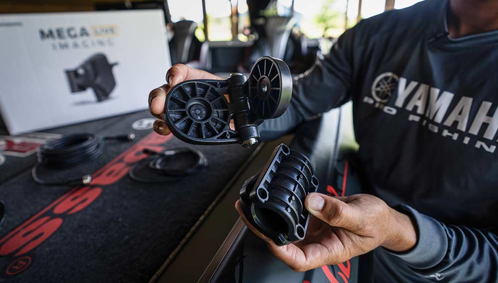
Use the following instructions to install the MEGA Live mount onto the transducer.
Determine if the transducer will be installed on the left or right side of the trolling motor.
If the trolling motor stows on the right (starboard) side of the boat, you will mount the transducer on the right (starboard) side of the trolling motor shaft.
If the trolling motor stows on the left (port) side of the boat, you will mount the transducer on the left (port) side of the trolling motor.
The MEGA Live mount should be open to begin the installation. Unlock the mount by pressing down on the two silver release buttons, and pull the mount open. It will re-lock automatically once fully opened. Trying to open the mount without depressing the two silver buttons may result in damage to the transducer mount.
With the transducer face down and its cables pointed away from you, determine how the MEGA Live mount should align with the transducer.
Recommended Configuration: Align the mount with the hinge on the left for a Port installation or on the right for a Starboard installation. Refer to the installation guide for greater detail.
Tip: In some installations, MEGA Live will be used alongside MEGA 360 Imaging and will need more clearance between the bottom of the MEGA 360 pod in order to utilize Landscape Mode. Especially on 45” shafts motors, we recommend that you check these clearances by completely rotating MEGA Live and deploying it into Landscape Mode to ensure that it will not make contact with the MEGA 360 pod.
If required, mount the MEGA Live transducer with the mounting hinge on the bottom, allowing the transducer to pivot down and further away from MEGA 360 (like shown).
Connect the MEGA Live mount to the transducer according to your Recommended or Optional configuration. The ratchets are keyed to allow for Port or Starboard installation. The ribs on the MEGA Live mount ratchet should align with the marks on your transducer.
Secure the MEGA Live mount to the transducer with one of the included lock washers and ¼"-28 screws, using the provided hex key. Hand tighten the screw until the lock washer is fully compressed, and then tighten an additional 1/4 turn. Hand tighten only to avoid potential damage.
Step 3: Install the Shaft Mount
Fold the MEGA Live mount back down using the release buttons to begin the next step.
Align the keys on the shaft mount and the MEGA Live mount to connect them. Secure the shaft mount with one of the included lock washers and ¼"-28 screws, using the provided hex key. Hand tighten the screw until the lock washer is fully compressed, and again hand tighten an additional 1/4 turn.
Rotate the shaft mount until it is aligned vertically with the transducer.
Step 4: Install the Shaft Clamp
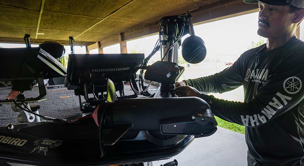
The trolling motor should be in the fully stowed (flat) position on the boat deck to begin this step of the installation.
Align the shaft mount and MEGA Live mount clamp around the base of the trolling motor shaft. Optional: The transducer can be installed farther up the trolling motor shaft if desired, when not installed alongside MEGA 360 Imaging.
Secure the shaft clamp to the shaft mount by installing the (4) #10-32 screws into the threaded holes on the clamp using the provided 5/32" hex key. Do not fully tighten, yet.
Rotate the MEGA Live Imaging transducer around the shaft until it is parallel with the lower unit of the trolling motor. Important: Make sure the transducer is pointing in the same direction as the trolling motor so you can understand the direction of your MEGA Live sonar beam while fishing.
Fully tighten the screws until the transducer cannot be moved on the shaft. Hand-tighten only!
Step 5: Route the Cables
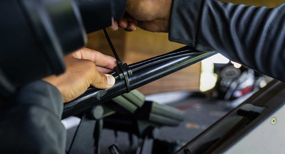
MEGA Live comes with molded anchor points along the power and Ethernet cables for easy rigging and to help protect the cable.
Connect the first anchor point roughly 4-5 inches from the top of the mount using one of the provided cable ties. Do not fully tighten, yet.
Caution: To avoid damaging the cables, apply cable ties ONLY at the designated anchor points.
Rotate the transducer by hand to test the Down, Forward, and Landscape Mode views as illustrated in MEGA Live Views to ensure proper slack in the cables. Your trolling motor mount includes guides to help you position the transducer correctly (see the MEGA Live Mode illustrations)
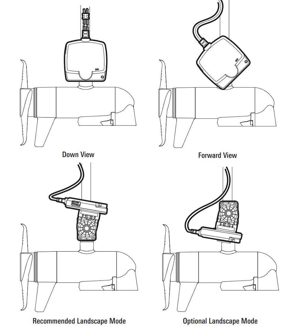
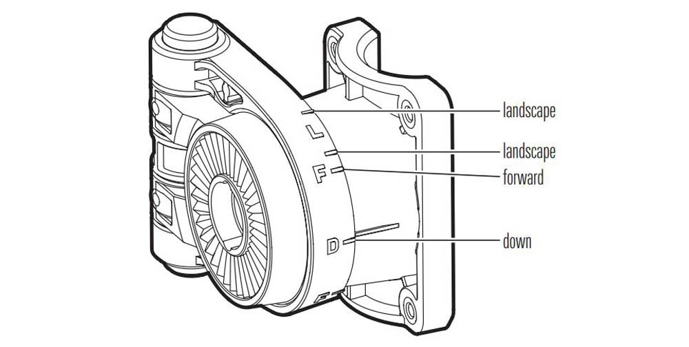
To alternate between Down and Forward views, rotate the transducer on its mount using both hands.
To change from Down or Forward view to Landscape Mode, press the two silver release buttons on the mount until the mount unlocks. Flip the transducer out until the hinge locks.
To adjust the Landscape Mode angle, rotate the transducer on its mount using both hands.
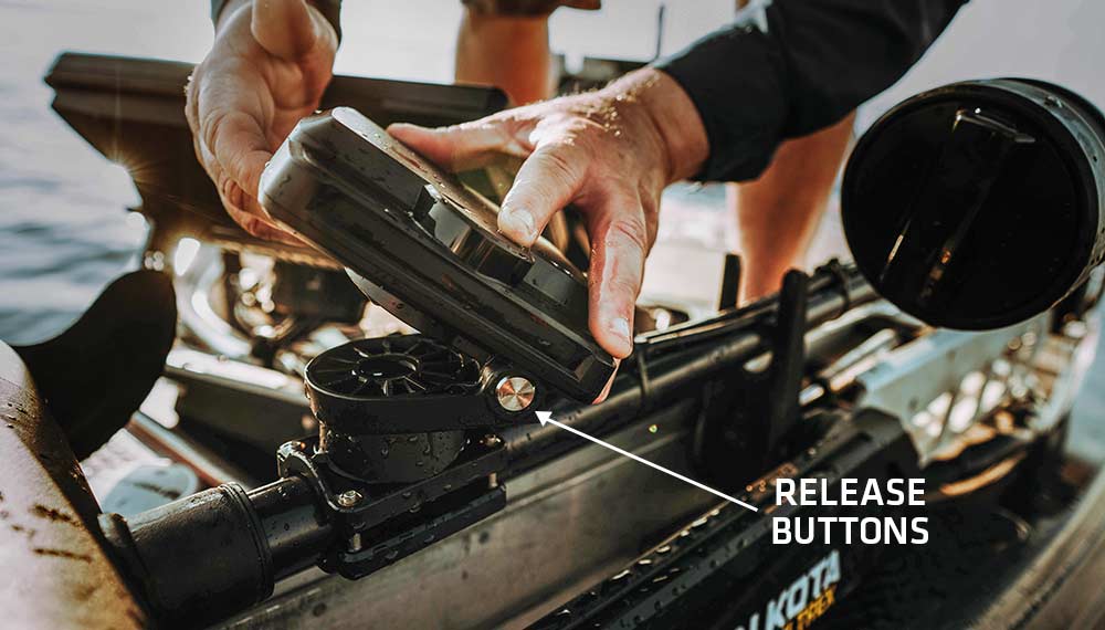
Adjust the first anchor point as needed to provide only enough slack cable for changing views, without binding the cable. Then fully tighten the cable tie to secure the cables to the shaft.
Secure the remaining anchor points with cable ties as you route the cables up the trolling motor shaft. Depending on your installation configuration and motor’s shaft length, you may not need all five anchor points.
Important: The cables should be routed through an established routing system on the boat, in an area with minimal interference. Inspect the selected route carefully to ensure that there are no sharp edges, obstacles, or obstructions that may damage the cables. Avoid pinch points created by stowing or deploying the trolling motor.
Route the rest of the cables to the side of the trolling motor, over the bow, to the chosen connection locations established in Step 1, Preparation for Installation.
Additionally, make sure to leave sufficient slack in the cables to allow for full movement of the trolling motor during normal operation. This can be checked before installing the final cable ties to the base of the motor and inside the deck of the boat. Ask someone for help to slowly deploy the motor and rotate the motor fully to the left and right by grabbing the lower unit. Pay close attention to the MEGA Live cables and that they have enough slack to allow the motor to steer fully left and right. Once established, secure a cable tie and carefully stow the motor.
Step 6: Connecting Ethernet and Power
Ethernet: Connect the 20’ foot Ethernet cable to the matching connector on MEGA Live sonar transducer. Locate the 10’ power cable and connect it to the MEGA Live transducer via the quick disconnect plug. Route the cables inside the boat as your installation requires. Once routed, insert the Ethernet Cable into the Ethernet port on the Humminbird control head (if running directly to the unit) or into a 5-Port Ethernet Switch. Additionally, make the necessary power connections to a 12-volt power source on the boat. Humminbird recommends connecting to a fuse-protected and switched power source.
Note: If you have a HELIX Series unit and plan to connect directly to the control head, you must connect the Ethernet Cable to an Ethernet Adapter Cable (AS EC QDE, separate purchase required). Insert the connector into the Ethernet port on the control head or cable tray. See your control head installation guide for details.
Step 7: Testing Out MEGA Live
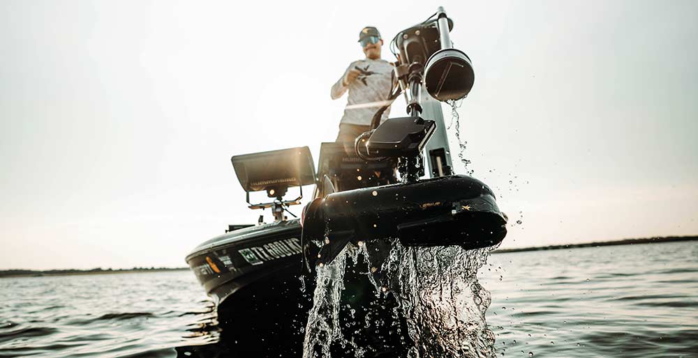
With MEGA Live installed on your boat, you will be ready to hit the water and see it in action. To test MEGA Live, power will need to be turned on to MEGA Live, the Humminbird unit and the 5-port Ethernet Switch (if equipped). In order to test the transducer, the integrated wet switch on the transducer will need to be activated by deploying it into water. Once in the water, you will be ready to start catching fish with MEGA Live Imaging.
Tip: If you try to test MEGA Live out of water, it will not turn, nor will it be recognized on the network. This is a designed feature of MEGA Live and does not indicate a product malfunction.